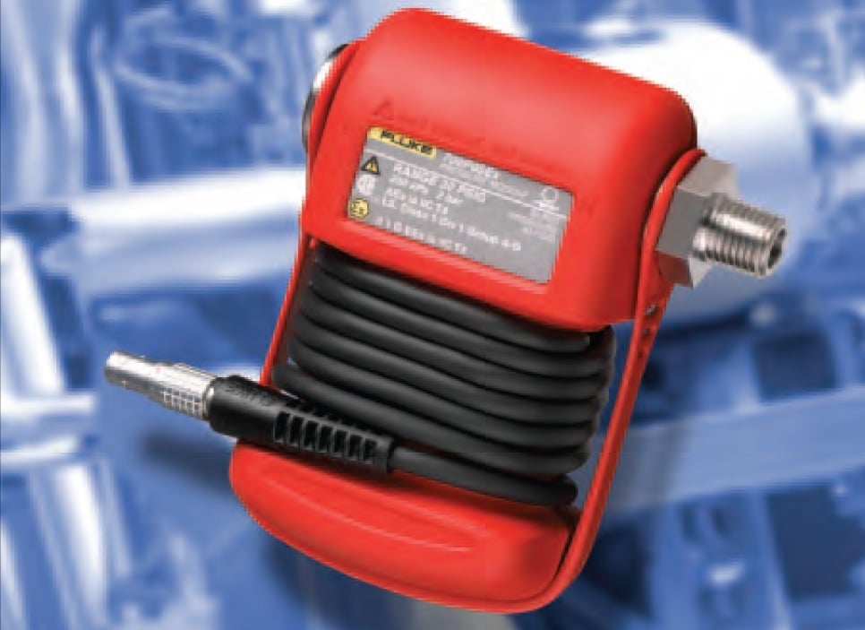
Pressure calibration can be challenging in the best of environments. Working in an area that has the potential for explosion takes the degree of difficulty to another level - one where the technician needs proper training and equipment.
To conduct pressure calibrations in potentially explosive environments, you need a pressure calibrator that is certified as intrinsically safe. Devices certified as "intrinsically safe" are designed to be unable to release sufficient energy, by either thermal or electrical means, to cause ignition of flammable material (gas, dust/particulates).
What is “intrinsically safe?”
Intrinsic safety is a protection method employed in potentially explosive atmospheres. Devices certified as “intrinsically safe” are designed to be unable to release sufficient energy, by either thermal or electrical means, to cause ignition of flammable material (gas, dust/ particulates).
Intrinsically safe standards apply to all equipment that can create one or more of a range of defined potential explosion sources:
- Electrical sparks
- Electrical arcs
- Flames
- Hot surfaces
- Static electricity
- Electromagnetic radiation
- Chemical reactions
- Mechanical impact
- Mechanical friction
- Compression ignition
- Acoustic energy
- Ionizing radiation
Intrinsic safety is particularly important for technicians working in the petrochemical and pharmaceutical industries, around bulk materials such as grain, in mining, or in any environment where explosive gases are present. The importance of safety in these environments can't be stressed enough. It takes a very small amount of energy to cause an ignition. For example, igniting a mixture of hydrogen in air requires only 20 uJ of energy. Following required safety practices and using specially engineered intrinsically safe tools (such as the Fluke 718Ex Intrinsically Safe Pressure Calibrator) reduces the inherent risks involved in working working around these hazards.
Typical pressure applications include calibrating a P/I transmitter in a classified location and calibrating a pressure switch in a classified area.
Intrinsically safe pressure calibration
To conduct pressure calibrations in potentially explosive environments, you need a pressure calibrator that is certified as intrinsically safe. Intrinsically safe pressure calibrators, such as the Fluke 718Ex, must be certified in accordance with the European ATEX (“Atmosphères Explosibles,” French for explosive atmospheres) directive (![]() II 1 G Ex ia IIC T4) for use in Europe and NEC 500; I.S. Class 1, Division 1 areas Group A-D T4 for use in the U.S.
II 1 G Ex ia IIC T4) for use in Europe and NEC 500; I.S. Class 1, Division 1 areas Group A-D T4 for use in the U.S.
In addition to an intrinsically safe pressure calibrator, strict adherence to calibration procedures is recommended, including:
Lock out: Make sure the system is shut down and other workers are notified that a potentially dangerous operation will be taking place.
Tape off area: Tape the work area off to prevent workers from entering with potentially dangerous electrical devices (cell phones, handheld computers, non-intrinsically safe tools). Purge or vent the systems: Safely purge or vent the system to remove any gases that may remain.
Use a gas detector: In an environment where explosive gas may be present, the use of a gas detector is a prudent step before starting a pressure calibration. Gas “sniffers” are available for a wide variety of applications and from handheld to larger, carted models.
Calibrate: Perform your calibration using an intrinsically safe pressure calibrator.
Clean up and reactivate: At the conclusion of calibration, reverse the process and reactivate the system.
Pressure calibration
The 718Ex Pressure Calibrator has the ability to apply pressure to a pressure transmitter or pressure switch while simultaneously measuring the mA signal or switch contacts.
Typical Pressure Applications
How to calibrate a P/I Transmitter in a classified location
It is important to be familiar with intrinsically safe work practices before performing any maintenance task in a classified area where explosive gasses may be present. Be sure to take proper precautions and refer to the 718Ex users manual and Fluke 718Ex CCD before proceeding.
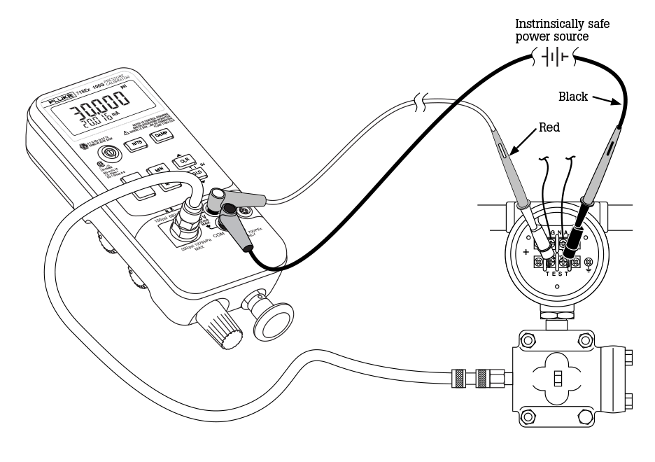
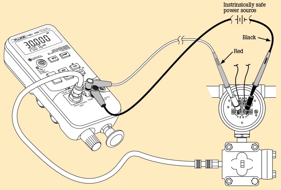
With a built-in hand pump, precision measurement of both pressure and current, the Fluke 718Ex Pressure Calibrator is a complete, self-contained tool for the calibration of P/I transmitters. To calibrate a 3 psi to 15 psi/4 mA to 20 mA transmitter using a Fluke 718Ex 30G Pressure Calibrator:
- Depressurize and isolate the transmitter. If opening the transmitter exposes voltages beyond the Instrinsic Safe (I.S.) rating use a continuous monitoring gas detector to monitor for explosive gases.
- Plumb the transmitter to the 1/8 inch NPT pressure port of the 718Ex. Connect the test leads per the figure above.
- Turn the calibrator on. Vent the calibrator and press zero to zero the pressure displayed. Close the vent control.
- Press the UNITS key until PSI shows in the display.
- With the 718Ex’s bleed valve open to atmosphere, press the ZERO key. Close the bleed valve. Set the pressure / vacuum valve to +, for positive pressure.
- Use the hand pump to apply roughly 3 psi to the transmitter. Partial pump strokes will apply small increments of pressure. Use the fine-adjust knob to get reasonably close to 3.00 psi.
- Press the HOLD key, and record the psi and mA readings. Press the HOLD key to resume reading.
- Calculate and record the error, using: Error = ([(i-4)/16] – [(P-3)/12]) * 100 where Error is in % of span, i is your measured current in mA and P is your measured pressure in psi.
- Repeat steps 5 through 7 at mid-range, around 9 psi, to check linearity at mid-span.
- Repeat steps 5 through 7, now at 15 psi, for a check at 100 % of span.

If your calculated errors are within tolerance, the transmitter has passed your As-found test, and you are done. If necessary, perform your zero and span adjustments, then repeat steps 5 through 9 for an As-left test. Depressurize the line, and disconnect the 718Ex. Continue to monitor for explosive gas until the transmitter is returned to service and all non-I.S. voltages or energy sources are isolated from exposure to the classified environment.
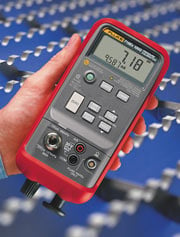
Measuring less than 9 inches in length and weighing just over two pounds, the rugged 718Ex is easy to carry into the field. The 718Ex is offered in both 30 psi and 100 psi models. Media compatibility is dry air and non-corrosive gasses. A built-in pump generates pressure or vacuum. Min, Max, and Hold functions are available. The 718Ex can also measure pressure using any of the Fluke 700PEx Pressure Modules, to cover applications up to 3,000 psi. The 718Ex comes complete with protective holster, test leads, test clips, Users Manual, and one 9-volt battery (installed).
| Pressure | mA | |||||
|---|---|---|---|---|---|---|
| Model | Range | Resolution | Accuracy | Range | Resolution | Accuracy |
| Fluke 718Ex 30G | -12 to 30 psi | 0.001 psi | 0.05 % FS | 0 to 24 mA | 0.001 mA | 0.02 % + 2 count |
| Fluke 718Ex 100G | -12 to 100 psi | 0.01 psi | 0.05 % FS | 0 to 24 mA | 0.001 mA | 0.02 % + 2 count |
| Fluke 718Ex 300G | -12 to 300 psi | 0.01 psi | 0.05 % FS | 0 to 24 mA | 0.001 mA | 0.02 % + 2 count |
How to use the 718Ex to calibrate a pressure switch in a classified area
It is important to be familiar with intrinsically safe work practices before performing any maintenance task in a classified area where explosive gasses may be present. Be sure to take proper precautions and refer to the 718Ex users manual and Fluke 718Ex CCD before proceeding.
- Depressurize and isolate the pressure switch from the process. If opening the switch exposes voltages or energy that is not intrinsically safe, use a continuously monitoring gas detector to monitor for the presence of explosive gasses.
- Plumb the 718Ex and make connections as per the illustration.
- Turn on the 718Ex and open the vent valve. Press the Zero button to clear the zero offset. Close the vent.
- Press the Switch Test button to enter the switch test mode.
- Apply pressure slowly with the hand pump until you approach the setpoint. Using the fine adjust vernier adjust the pressure until the switch opens and OPEN is displayed on the 718Ex.
- Release the pressure slowly using the fine adjust vernier until RCL is displayed.
- Press the Switch Test button once to read the pressure values for switch opening and again to see the pressure at switch closing.
- Press and hold the Switch Test button for 3 seconds to clear the test results and start over.
- Adjust the pressure switch setpoint until the switch contacts open and close at the desired pressure.
- Continue to monitor for explosive gasses until the switch is returned to service and all non-IS voltages or energy sources are isolated from exposure to the classified environment.
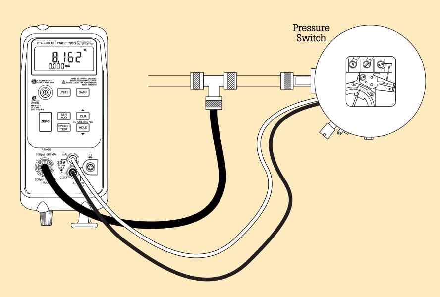
Pressure switch calibration
Verify the setpoint and deadband of pressure switches using the 718Ex Pressure Calibrators.
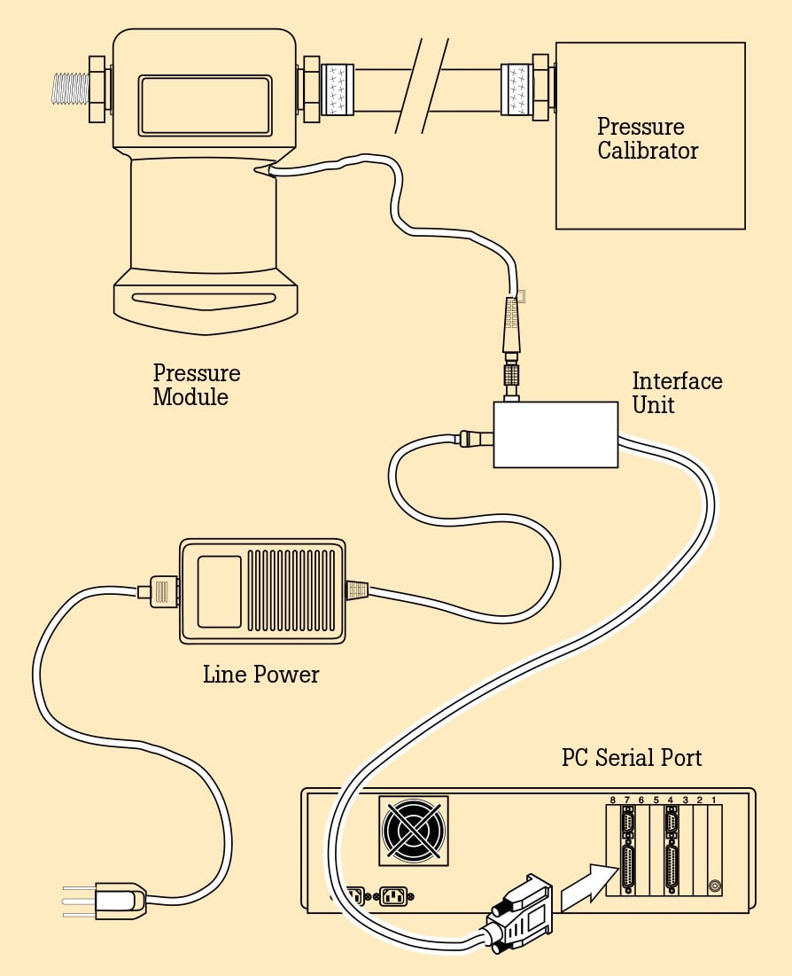
Fluke 700 PCK Calibration Kit
The Fluke 700PCK Pressure Calibration Kit makes it possible to calibrate your pressure modules at your facility using your own precision pressure standards. The kit consists of a power supply, an interface adapter, appropriate cables, and Fluke 700PC Pressure Module Calibration software. When installed on your PC, the Windows®-based software easily steps you through an as-found verification, a calibration adjustment, and an as-left verification. Calibration data is captured for import to your database. A 386 or better PC, running Windows 3.1, or later is required, along with a precision pressure standard with an uncertainty of less than 1/4 that of the pressure module being verified.
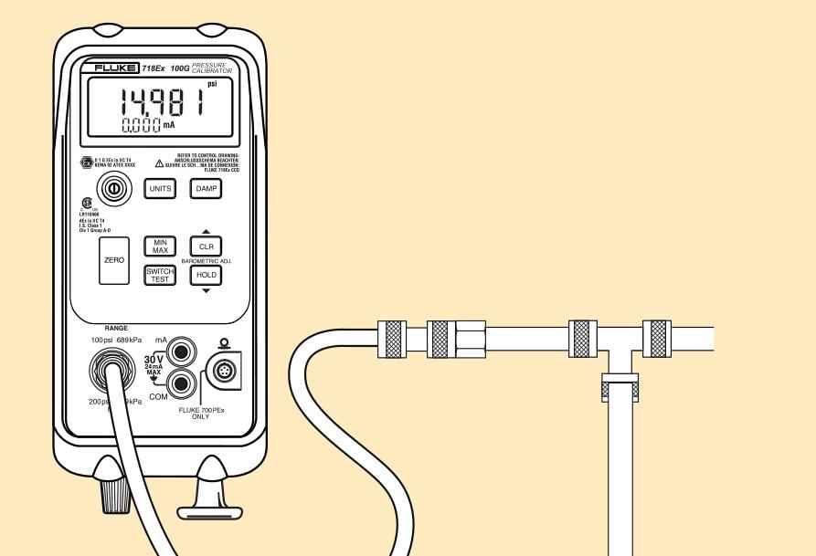
Measuring pressure
To measure pressure, the appropriate pressure module for the pressure to be tested is attached to the calibrator. The measured pressure can be displayed in a variety of engineering units. Here, a Fluke 718Ex Pressure Calibrator is shown.
P to I device calibration
The P to I device is used to convert pneumatic analog loop control signals of 3 psi to 15 psi to electrical loop analog control signals of 4 mA to 20 mA. Here, a Fluke 718Ex Pressure Calibrator is used.
Sourcing pressure
To calibrate an instrument with a pressure input, pressure from the onboard pump can be used. Pressures from -12 to 30 psi or -12 to 100 psi can be generated by the internal pump. The integral fine adjust vernier allows pressures to be adjusted with precision. Here, a Fluke 718Ex Pressure Calibrator is shown.
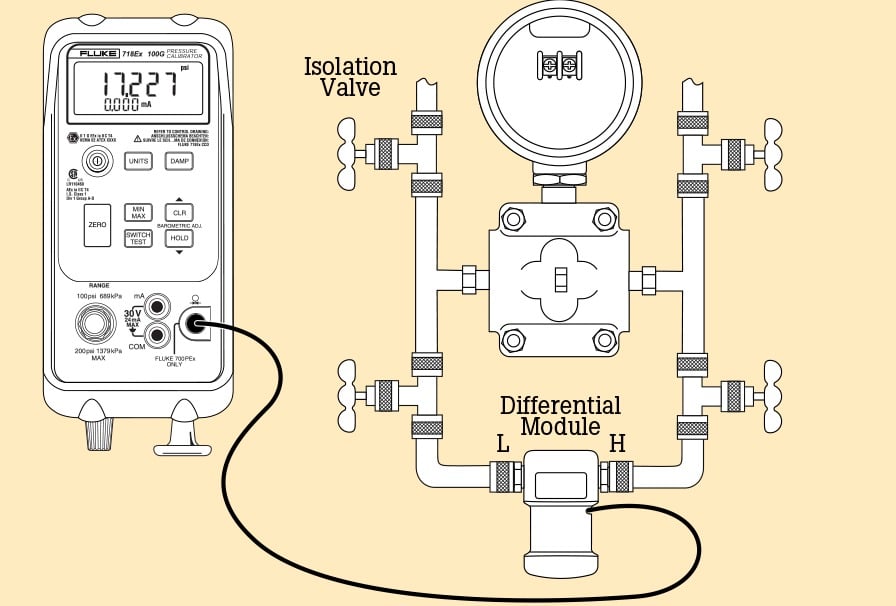
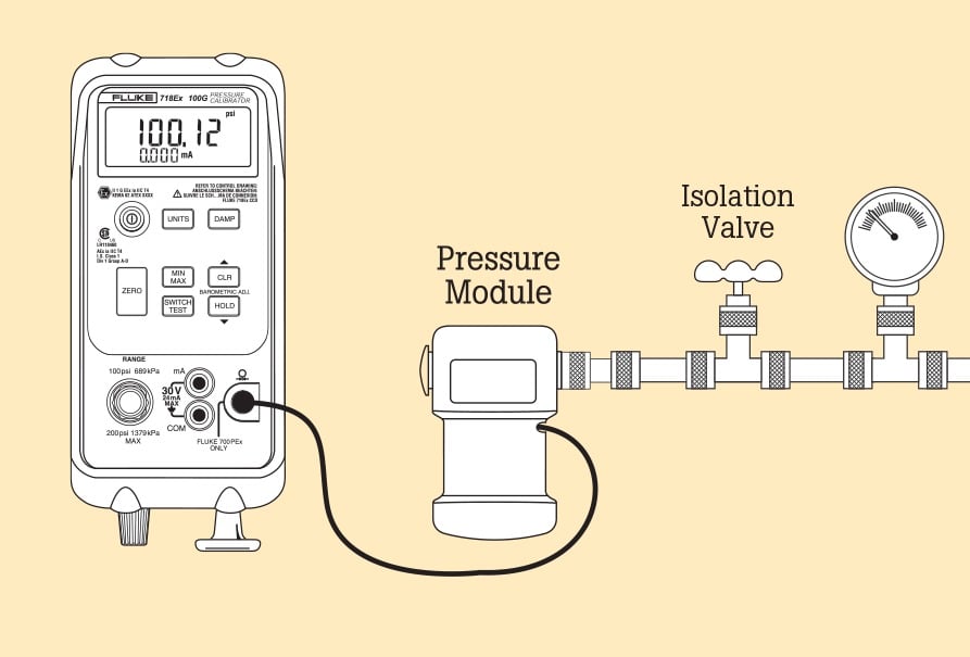
Differential measurements
Differential pressure modules are useful in a wide variety of applications, e.g., measuring the fluid level in a tank or calibrating a differential pressure transmitter. A Fluke 718Ex Pressure Calibrator is shown using one of the 700PEx accessory pressure modules.
Specifications
| Pressure specifications (internal sensor) | ||
|---|---|---|
| Pressure Input (18 °C to 28 °C, one year) | ||
| Range | Resolution | Accuracy |
| -12–30 psi (207 kPa) | .001 psi (0.01 kPa) | .05 % FS |
| -12–100 psi (690 kPa) | .01 psi (0.1 kPa). | .05 % FS |
| -12–300 psi (2070 kPa) | .01 psi (0.1 kPa) | .05 % FS |
| Temp Coeff. -10 to 18 °C, 28 to 55 °C | + .01 % of range per °C | |
| Engineering Units (in Hg) | ||
| PSI, in. H2O (4 °C), in. H2O (20 °C), kPa, cm H2O (4 °C), cm H2O (20 °C), BAR, mBAR, kg/cm2, mmHg, in Hg | ||
| Media | ||
| Gasses (non corrosive) | ||
| Overpressure | ||
| 3 x F.S. on 30G 2 x F.S. on 100G 375 psi on 300G | ||
| Operating modes | ||
| Measure pressure (using internal sensor) | ||
| Display pressure module reading (automatically selected when pressure module connected) | ||
| Measure current | ||
| Input/output | ||
| Pressure input | 1/8 in. NPT pressure fitting | |
| Pressure module input | LEMO connector | |
| Current input | Shrouded banana jacks | |
| Battery | ||
| Power | One 9-volt alkaline battery ANSI/NEDA 1604A or IEC 6LR619V | |
| Battery life | 4 to 20 hours, depending on functions used | |
| Current specifications (18 °C to 28 °C, one year) | ||
| Current Measurement | ||
| Range | 0 to 24 mA | |
| Resolution | .001 mA | |
| mA ± 5 °C | .02 % Rdg ± 2 count | |
| Temp Coeff. to 18 °C, to 55 °C | ± .005 % of range per °C | |
| Zeroing modes | ||
| Gage and differential | Pushing Zero button stores present pressure value as an offset and subtracts it from the displayed value | |
| Absolute | Pushing Zero button causes nominal barometric pressure to be displayed. User corrects to actual barometric pressure with up/down keys. Difference is used as zero offset calibration. | |
| Environmental and safety requirements | ||
| Operating temperature | -10 °C to 55 °C | |
| Non-operating temperature | -40 °C to 60 °C | |
| Relative humidity (%RH operating without condensation) | 95 % (10 to 30 °C) 75 % (30 to 40 °C) 45 % (40 to 50 °C) 35 % (50 to 55 °C) | |
| Dimensions (LxWxD) | 216 mm x 94 mm x 66 mm (8.50 in x 3.72 in x 2.60 in) | |
| Weight | 35 oz (992 g) | |
| Vibration | Random, 2g, 5-500 Hz | |
| Shock | 1 Meter Drop test | |
| Safety | I.S. Class I Div 1 Groups A-D T4AEx ia IIC T4 II 1 G Ex ia IIC T4 KEMA 04 ATEX 1061 Ta = -10 °C to +55 °C | |
| EMC | EN61326 2002-02, Criteria C | |
Pressure Modules
The I.S. family of pressure modules
A family of 8 Intrinsically Safe pressure modules covers the most common pressure calibrations from 0-10” H2O (0-2.5 kPa) to 0-3,000 psi (0-20,000 kPa).
Gage pressure modules have one pressure fitting and measure the process pressure with respect to atmospheric pressure. Differential pressure modules have two pressure fittings and measure the difference between the applied pressure on the high fitting versus the low fitting. Each module is clearly labeled for range, overpressure specification, and media compatibility. A metric adapter is included with all but the P29Ex high pressure Ex module.
Quick and easy measurements
Fluke 700PEx Series pressure modules are easy to operate. To measure pressure, the technician plumbs the pressure module to a pressure source, and connects the pressure module cable to the calibrator. Pressure is applied, measured by the pressure module, and displayed digitally on the calibrator. At the touch of a button, the pressure may be displayed in up to 11 different engineering units.
Pressure module performance
Fluke 700PEx Series pressure modules are highly accurate, with total specifications that apply from 0 % to 100 % of full span and from 0 °C to 50 °C (32 °F to 122 °F)—a feature that sets them apart from other pressure calibrators. Many ranges have total uncertainties of 0.05 % of full scale and reference uncertainties of 0.025 % of scale (see table below).
Rugged construction
A urethane overmolding protects against shock if a module is accidentally dropped and also seals against dirt, dust, and moisture. Pressure connections are 1/4˝ NPT. A BSP/ISO adapter is also provided on all but the P29Ex.
Convenient setup
A one-meter cable between the pressure module and calibrator reduces the length of connecting tubing to the pressure source. The remote pressure head also provides an extra margin of safety and convenience by removing the calibrator and operator from the pressure source.
700PEx:
![]() I.S. Class I Div 1 Groups A-D T4 AEx ia IIC T4
I.S. Class I Div 1 Groups A-D T4 AEx ia IIC T4
![]()
![]() II 1 G Ex ia IIC T4 Ta = 0 °C to +50 °C
II 1 G Ex ia IIC T4 Ta = 0 °C to +50 °C
Pressure module specifications
(All specifications in % of full span. Specifications reflect a confidence interval of 95 %.)
| Model | Range/ Resolution | Range (approx)/ Resolution | Reference uncertainty (23 ± 3 ºC) | Stability (1 year) | Temperature (0 to 50 ºC) |
|---|---|---|---|---|---|
| Differential | |||||
| FLUKE-700P01Ex | 10 in. H2O/0.01 | 2.5 kPa/0.002 | 0.200 | 0.050 | 0.050 |
| FLUKE-700P24Ex | 15 psi/0.001 | 103 kPa/0.01 | 0.025 | 0.010 | 0.015 |
| Gage | |||||
| FLUKE-700P05Ex | 30 psi/0.001 | 207 kPa/0.01 | 0.025 | 0.010 | 0.015 |
| LUKE-700P06Ex | 100 psi/0.01 | 690 kPa/0.07 | 0.025 | 0.010 | 0.015 |
| FLUKE-700P27Ex | 300 psi / 0.01 | 2070 kPa / 0.1 | 0.025 | 0.010 | 0.015 |
| FLUKE-700P09Ex | 1500 psi/0.1 | 10 MPa/0.001 | 0.025 | 0.010 | 0.015 |
| FLUKE-700P09Ex | 1500 psi/0.1 | 10 MPa/0.001 | 0.025 | 0.010 | 0.015 |
| Absolute | |||||
| FLUKE-700PA4Ex | 15 psi/0.001 | 103 kPa/0.01 | 0.050 | 0.010 | 0.010 |
| High | |||||
| FLUKE-700P29Ex | 3000 psi/0.1 | 20.7 M Pa/0.001 | 0.050 | 0.010 | 0.020 |
| Model | Total1 uncertainty | High2 side media | Low2 side media | Fitting material | Max over-pressure (x nominal) |
| Differential | |||||
| FLUKE-700P01Ex | 0.300 | Dry | Dry | 316 SS | 3x |
| FLUKE-700P24Ex | 0.050 | 316 SS | Dry | 316 SS | 3x |
| Gage | |||||
| FLUKE-700P05Ex | 0.050 | 316 SS | N/A | 316 SS | 3x |
| LUKE-700P06Ex | 0.050 | 316 SS | N/A | 316 SS | 3x |
| FLUKE-700P27Ex | 0.050 | 316 SS | N/A | 316 SS | 3x |
| FLUKE-700P09Ex | 0.050 | 316 SS | N/A | 316 SS | 2x |
| FLUKE-700P09Ex | 0.050 | 316 SS | N/A | 316 SS | 2x |
| Absolute | |||||
| FLUKE-700PA4Ex | 0.070 | 316 SS | N/A | 316 SS | 3x |
| High | |||||
| FLUKE-700P29Ex | 0.080 | C276 | N/A | C276 | 2x |
1 Total uncertainty, one year for temperature range 0 °C to +50 °C. Total uncertainty, 1.0 % of full span for temperature range -10 °C to 0 °C. 2 “Dry” indicates dry air or non-corrosive gas as compatible media. “316 SS” indicates media compatible with Type 316 Stainless Steel. “C276”indicates media compatible with Hastelloy C276. | |||||
Pressure Accessories
Fluke 700PTP-1 Pneumatic Test Pump
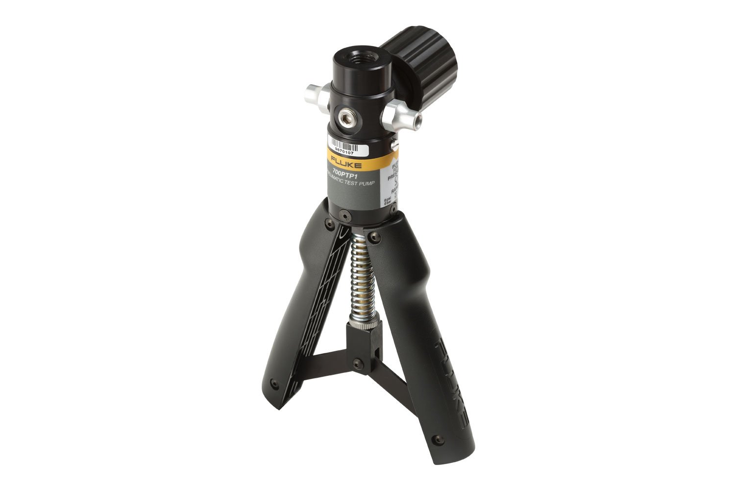
For use with: Fluke 700 Series Pressure Modules and the Fluke 710 Series Pressure Calibrators.
Description: The Fluke 700PTP-1 is a handheld pressure pump designed to generate either vacuum to -11.6 psi/ -0.8 bar or pressure to 600 psi/ 40 bar. The Fluke 700PTP-1 has two pressure ports:
- 3/8-BSP (ISO228) female parallel thread fitting for the reference gauge or pressure module
- 1/8-BSP (ISO228) female parallel thread fitting for the unit under test
Application: The Fluke 700PTP-1 features an integral pressure adjustment vernier which varies the pressurized volume by 2.0 cc over approximately eleven turns of the vernier knob. The pressure variation achievable with the vernier will depend on the nominal pressure and total pressurized volume, but with a minimum volume and maximum pressure, the vernier provided 600 ± 20 psi adjustment range. With a minimum volume and no pressure applied, the vernier can also be used to provide a 0 to 70” H2O range. Larger volumes will provide a smaller range of adjustment, but greater resolution. The length of the stroke can be adjusted to limit the maximum output pressure. Maximum output pressure is adjustable from 2.5 psi to 600 psi.
Fluke 700HTP-1 Hydraulic Test Pump
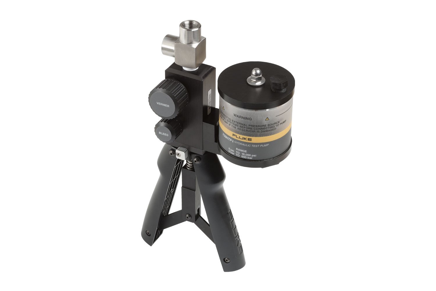
For use with: Fluke 700 Series Pressure Modules and the Fluke 710 Series Pressure Calibrators.
Description: The Fluke 700HTP-1 is designed to generate pressures up to 10,000 psi/700 bar. The Fluke 700HTP-1 has two pressure ports:
- 3/8-BSP (ISO228) female parallel thread fitting for the reference gauge or pressure module
- 1/8-BSP (ISO228) female parallel thread fitting for the unit under test
Note: The user must provide a hose with appropriate end fittings from this port to the unit under test, such as the Fluke-700HTH Test Hose.
Application: This pump can provide up to 10,000 psi using distilled water or mineral-based hydraulic oil. The pump is operated by pumping several strokes to prime the system, then switching to high pressure mode when the resistance increases. An integral pressure adjustment vernier knob varies the pressurized volume by 0.6 cc. The pressure variation achievable with the vernier will depend on the nominal pressure and total pressurized volume, but with a minimum volume, the vernier provided 150-3,000 psi (at 150 psi nominal) and 3,000-10,000 psi (at 3,000 psi nominal) adjustment ranges. With a minimum volume and no pressure applied, the vernier can also be used to provide a 0 to 1.7 psi range. Larger volumes will provide a smaller range of adjustment, but greater resolution.
Fluke 700LTP-1 Low-Pressure Test Pump
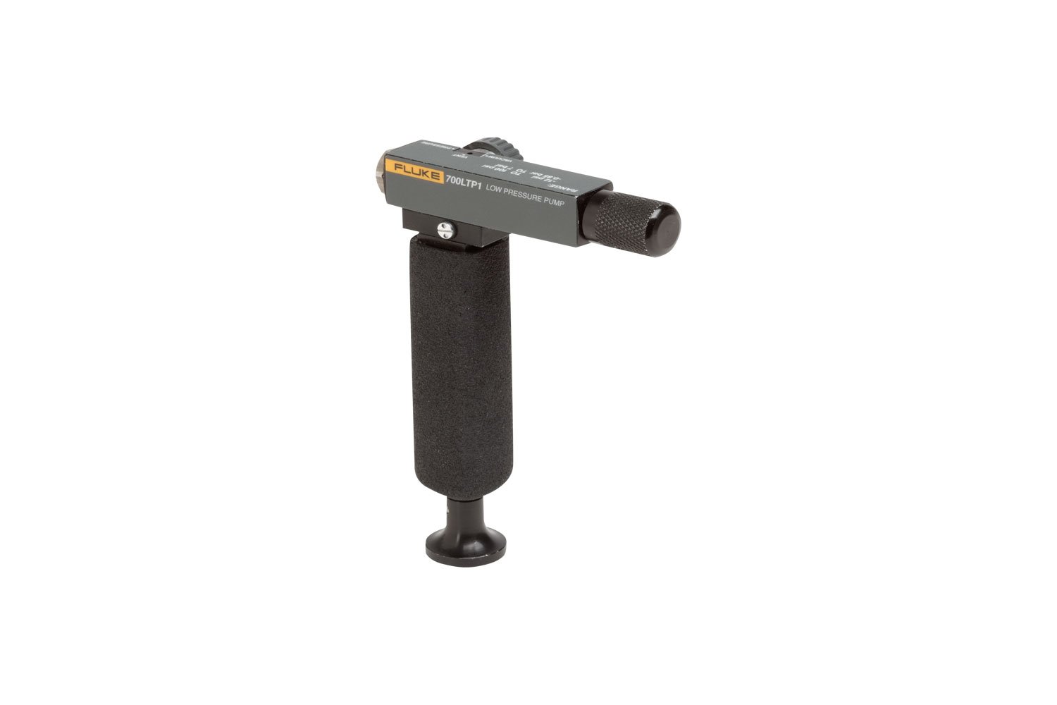
Description: The Fluke 700LTP-1 is a hand operated pressure pump designed to generate either vacuum to -12 psi/-.85 bar or pressures to 20 psi/2000 mbar. The Fluke 700LTP-1 has two pressure ports with push fit connectors. These push fit connectors, one for the reference port for connection to a Fluke 700 series pressure module and one to connect to a unit under test, connect to the supplied test hoses. These test hoses are terminated with 1/4-BSP (ISO228) female parallel thread fittings that can be adapted using the fittings included.
Application: The Fluke 700LTP-1 is primarily intended for low pressure applications. It features a fine adjust vernier with .00145/PSI resolution at low pressures. The pressure variation achievable with the vernier will depend on the nominal pressure and total pressurized volume, but with minimum volume and maximum pressure the vernier provides 30 psi ± 6 psi. The adjustable pressure relief valve features a slow-bleed capability that allows the user to slowly release pressure at a controlled rate to achieve a desired pressure.
Pressure Terminology
Absolute pressure—absolute pressure measurements are referenced to zero pressure, (a perfect vacuum.)
Absolute pressure transducer— a transducer that has an internal reference chamber sealed at or close to zero pressure (full vacuum) when exposed to atmosphere a reading of approximately 14.7 psi results.
Boyle’s Law—the volume of a gas is inversely proportional to the pressure of the gas at constant temperature: V=1/P.
Charles’ Law—essentially states for a fixed volume of gas, if the temperature is raised, the pressure will increase. P = Constant x T.
Common mode pressure—the underlying common pressure (or static pressure) within a system from which a differential measurement is being made.
D/P: Differential pressure, (pronounced DP)—other names used to mean the same thing are d/p cell, d/p transmitter and ΔP transmitter (where Δ is delta or differential). This is the most common type of transmitter used in most process industries. It can be used to measure level, flow, pressure, differential pressure, and density or specific gravity. With some modifications, it can measure such things as temperature and oxygen purity. The d/p transmitter can be pneumatic, electromechanical, or solid state. It can also be a smart transmitter. A typical large process plant can have hundreds or thousands of d/p transmitters in service.
Gage pressure—the pressure relative to atmospheric pressure. Gage pressure = absolute pressure minus one atmosphere.
Gage pressure transducer— a transducer that measures pressure relative to atmospheric pressure.
Ideal Gas Law—combining Boyle’s Law and Charles’ Law, results in the Ideal Gas Law: PV=nRT, where nR is constant for a particular gas analogous to the number of molecules and the relative size of the molecule.
I/P (I to P)—a current to pressure transmitter. A common instrument in modern industrial plants. A typical large paper mill or refinery could have 5,000 I/Ps in use.
Line pressure—the maximum pressure in the pressure vessel or pipe for differential pressure measurement.
Orifice plate—a very low cost and common primary sensing element (PSE) for measuring flow. It must be used in conjunction with a d/p cell. It creates a venturi and a resulting P is developed across the plate whose square root is proportional to flow.
P/I (P to I)—a pressure to current transducer.
Pneumatic relay—refers to a pneumatic instrument that performs a function to its input and provides the result on its output (Example: square root extractor, adder, etc.).
PSI—pounds per square inch (same as psig).
PSIA—pounds per square inch absolute.
PSID—pounds per square inch differential.
PSIG—pounds per square inch gage (same as psi).
Square root extractor—an instrument or software program that takes the square root of input and puts the result on its output. Square root extraction is needed to linearize many flow signals. Example: orifice plates, venturis, target flow meters, and pitot tubes all require the transmitter’s output signal to be linearized. Mag flow meters, turbine flow meters, Doppler flow meters, and vortex shedding flow meters don’t require square root extraction.
Static pressure—the zero-velocity pressure at any arbitrary point within a system.
Wet/dry differential—a differential pressure transducer or transmitter that uses a metal diaphragm at the wet port where fluids can be applied, and no diaphragm at the dry port. The dry port exposes the sensor material to the medium, so only clean dry gas can be applied to this port.
Wetted parts—the diaphragm and pressure port material that comes in direct contact with the medium (gas, liquid).