- Other Fluke companies:
- Fluke
- Fluke Biomedical
- Fluke Networks
- Fluke Process Instruments
Temperature & Humidity Environmental Controls in a Primary Standards Laboratory
ISO 17025, Section 5.3, requires the control, monitoring and recording of laboratory environmental conditions as required by relevant specifications, methods and procedures, or where they influence the quality of the results. But what happens when your laboratory’s environmental control system (aka air-conditioning system) gets old, cranky and hard to maintain? What happens when out-of-tolerance (OOT) conditions for temperature or humidity (or sometimes both simultaneously) begin happening with some regularity?
Fluke’s Everett Primary Electrical Laboratory (EPEL), located in Everett, WA, is the company’s flagship electrical laboratory in the United States. It houses primary electrical standards and performs high-end calibrations in the areas of AC/DC voltage and current, resistance, RF, and capacitance. One key component is a Josephson Voltage Standard. If the EPEL is not operating then all of Fluke manufacturing and service may be shut down. Accordingly, the allowable temperature and humidity operating limits are fairly narrow: 23 °C ± 0.6 °C and 45 %RH ± 5 %RH, respectively. Complicating the issue is the layout of EPEL: Four non-symmetrical rooms, with varying heat loads. This lab simply cannot afford downtime due to environmental OOT conditions. Yet such recurrences began increasing as the lab’s air-conditioning system aged. The solution became clear: Replace it.
This paper examines the successful selection and sizing of the replacement air-conditioning system, selection of a monitoring system, coordinating the lab’s downtime with customers, standards verification before and after the installation, placement of the controls and monitoring sensors, checking temperature gradients, eliminating hot and cold spots in the lab, and other considerations.
ABSTRACT
ISO 17025, Section 5.3, requires the control, monitoring and recording of laboratory environmental conditions as required by relevant specifications, methods and procedures, or where they influence the quality of the results. But what happens when your laboratory’s environmental control system (aka air-conditioning system) gets old, cranky and hard to maintain? What happens when out-of-tolerance (OOT) conditions for temperature or humidity (or sometimes both simultaneously) begin happening with some regularity?
Fluke’s Everett Primary Electrical Laboratory (EPEL), located in Everett, WA, is the company’s flagship electrical laboratory in the United States. It houses primary electrical standards and performs high-end calibrations in the areas of AC/DC voltage and current, resistance, RF, and capacitance. One key component is a Josephson Voltage Standard. If the EPEL is not operating then all of Fluke manufacturing and service may be shut down. Accordingly, the allowable temperature and humidity operating limits are fairly narrow: 23 °C ± 0.6 °C and 45 %RH ± 5 %RH, respectively. Complicating the issue is the layout of EPEL: Four non-symmetrical rooms, with varying heat loads. This lab simply cannot afford downtime due to environmental OOT conditions. Yet such recurrences began increasing as the lab’s air-conditioning system aged. The solution became clear: Replace it.
This paper examines the successful selection and sizing of the replacement air-conditioning system, selection of a monitoring system, coordinating the lab’s downtime with customers, standards verification before and after the installation, placement of the controls and monitoring sensors, checking temperature gradients, eliminating hot and cold spots in the lab, and other considerations.
1 INTRODUCTION & BACKGROUND
Environmental controls and monitoring are required in all calibration laboratories. The EPEL is monitored for temperature, humidity, pressure, line quality and radiated RF per 2 the Fluke Park Laboratory’s quality manual. This paper is concerned with the temperature and humidity aspects of environmental controls.
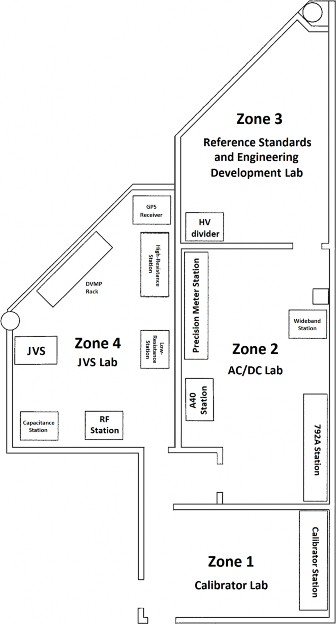
The Fluke Park campus was built in 1980, which included a four-room dedicated space, known as the Primary Standards Lab (PSL). Recently, owing to the addition of temperature and pressure manufacturing and calibration capability in Fluke Park, the PSL was renamed as the Everett Primary Electrical Laboratory (EPEL) to properly communicate its mission of electrical calibration, and to remove confusion with Fluke’s three other primary laboratories. The four EPEL rooms, however, remain the same today; see Figure 1
In 1980, when the laboratory was originally built, an air-conditioning pack was installed to handle the environmental controls. This proved unsatisfactory, and a purpose-built air-conditioning system was designed and installed in 1984. The replacement air-conditioning system is described here in modest detail since its design and eventual shortcomings drove the requirements for the system upgrade in 2011.
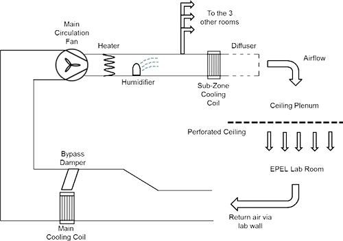
At the core of this system was a recirculating air loop that used a primary cooling coil for cooling and dehumidifying the supply air and a single, large fan to move the air. The cooling coil can be thought of as an oversize car radiator that works in the reverse direction. An air heater and humidifier, located downstream of the fan, were used to adjust the temperature and humidity of the air before its flow was split among the four EPEL rooms. A secondary cooling coil was installed above each room, and was used to fine-tune the air temperature according to each room’s needs. The air was then delivered into the pressurized plenums above each room’s ceiling thru an expanded-metal diffuser. The plenums of each room were isolated from each other.
The air flowed thru perforated ceiling tiles into each room. This provided a fairly uniform air supply into each lab room. Return air was via several wall-mounted exhaust grilles in each room to minimize hot or cold air pockets. The inside of the wall itself, between the studs, was used as part of the return circuit to minimize complexity due to ducting. The walls were painted with a sealer to greatly minimize the transfer of humidity across the outer boundaries of the lab. A schematic of the airflow system in shown in Figure 2.
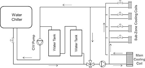
Also integral to this system was a chilled water system that cooled and dehumidified the air by use of the large primary cooling coil and four secondary cooling coils mentioned above. The water chiller was a dual-refrigeration system that was mounted on the roof of the building and had a total capacity of ten tons. A schematic of the chilled water system in shown in Figure 3.
The system was supplemented with an airflow bypass damper when the full function of the main cooling coil was not needed. In order to keep the lab at a slightly positive pressure, a small air supply line from the building’s central system was tapped into the lab’s supply side. This also served to keep the lab’s air from getting stale by use of the feed-and-bleed principle.
A Staefa control system regulated the chilled water supply to the five cooling coils, bypass damper position, and operation of the air heater and humidifier, as was necessary. The control system included four temperature sensors, each installed in one of the rooms, and shielded from the supply airflow. A single humidity sensor was also used.
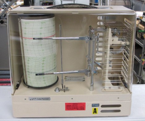
Manual controls were provided at the control panel to allow the lab Technicians to adjust the bypass damper. This enabled the “trimming” of the air supply to adjust lab temperature when the automatic controller was at its limit. A log was kept of these adjustments so that lab personnel always knew the damper adjustment. The controller provided a display of the temperature and humidity in each room, but did not record the data. Therefore, two hygrothermographs were used to record the temperature & humidity history of the lab (Figure 4).
In 1999 the hygrothermographs were replaced by one temperature sensor in each room, and one humidity sensor in Room 4, all connected to a Fluke NetDAQ data logger. Data recording was performed by TrendLink software.
Each monitoring sensor was co-located with each room’s control sensor, and was protected against direct airflow from the ceiling. The temperature monitoring sensors and the control system sensors were mounted together in a tube in an X configuration; a fan pulled air over the sensors – ensuring the sensors received the same input.
Over the years, this overall system served its purpose. However, as the system began to age, instances of OOT temperature and/or humidity conditions increased. High OOT temperature was usually a seasonal occurrence, primarily during the summer. Low OOT humidity could happen, even in the Pacific Northwest, whenever a northerly airflow developed.
In some cases, simple countermeasures could be employed. The air intake dampers were adjusted when a high OOT temperature condition began building. Portable humidifiers were used when humidity went low OOT and the air conditioning was unable to make up the difference.
However, when temperature went OOT, either high or low, the response usually was to stop all calibrations in the affected room(s), fix the problem, return to an in-tolerance state, and then soak the room(s) before resuming calibrations. Figure 5 is an example of a more extreme incident where different EPEL rooms were OOT high or low, within a relatively short period of time.
In all, the A/C system worked reasonably well for about 25 years, within the limitations of its design. However, its age began to show. In particular, the Staefa controller became unserviceable due to unavailability of replacement parts. Also, the capacity of the system did not allow for additional electronics being added to the lab spaces. Finally, the decision was made to perform a major upgrade.
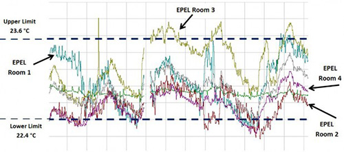
(two hours per division)
Capital funding was obtained for several laboratory upgrades in 2011; the single largest upgrade was to the air-conditioning system. Fluke Park Facilities organization was contracted to design the air-conditioning upgrade and supervise its installation.
2 DESIGN
Over the years, the amount of electronic-powered equipment in the lab, and the associated heat load, increased. Also, the heat load could vary from room to room and by time of day. The old system had a cooling capacity of 10 tons. After taking stock of the lab’s heat load in 2011, and projecting future growth, which included high-current shunts and amplifiers, it was decided to increase the capacity of the upgraded air-conditioning system to 20 tons. This, in turn, drove the decisions as to what system components to keep, and which to replace.
Since the old Staefa controller was no longer serviceable, it was replaced with a multi-channel Johnson Controls system and new sensors.
The chilled water chiller, chilled water control valve, chilled water pumps, all cooling coils, water tanks and control system were replaced. The air circulation fan, ducting, humidifier, air heater and much of the chilled water piping was retained, but refurbished where required. The replacement water chiller contained a variable-frequency compressor that made fine-tuning of the chilled water temperature possible.
The cooling coils were all increased in size to handle the larger heat load, matching the new water chiller. The chilled water pump capacity was increased slightly to provide higher flow, and the system redesign allowed the return chilled water to run at a higher temperature than before. Taken together, these changes allow the new air-conditioning system to use the full capacity of the 20 ton chiller.
The next problem was the delivery of the air into each room. As was previously noted, the old system supplied the conditioned air into positive pressure plenums above the ceiling. The ceiling tiles were perforated with several thousand holes per tile. This created a fairly uniform air wash that flowed down from the ceiling. Experience with this arrangement was favorable.
Since the old tiles were showing their age, an attempt was made to find a supplier of perforated ceiling tiles. However, such a product was not available and regular 2 ft by 4 ft tiles were used. The positive-pressure plenums above the ceiling were retained, but several ceiling supply vents were installed in each room.
While the Johnson Controls system included a separate temperature sensor in each room, those sensors were for control purposes only. A separate data recording system was still needed. Since the NetDAQ was getting old, it was decided to replace it with Fluke 1620A Thermo-Hygrometers (aka DewK) recording to LogWare software.
Finally, a link was designed to connect the Johnson Controls system to the Facilities control room in the building. This would serve to notify the Facilities and Security organizations in the event of an OOT condition in the lab, as Facilities has the responsibility for first response after an OOT condition. This was modeled after a similar design in the Customer Service lab (SSO) spaces in a nearby building.
3 UPGRADE & DOWNTIME
Since the air-conditioning upgrade was going to require laboratory downtime, advance planning and logistics would be required:
- Determination when the contractor would have all the new components on hand and be ready to start work
- Determination of how long the upgrade and system balancing would take
- Coordination with the lab’s customers, both within and outside of Fluke, regarding the scheduling of their critical calibration jobs
- Power-off verification tests of all standards and calibration stations
- Moving most of the lab equipment out of EPEL
- General painting (since the walls would be accessible)
- Moving the lab equipment back into EPEL
- Equipment acclimation
- Power-on verification tests of all standards and calibration stations
In all, about three weeks of downtime were experienced. Approximately one day was required to get the new air-conditioning system running, and approximately two more weeks to fine-tune it.
Concurrently with the above, a DewK and two sensors were installed in each room and connected to a PC acting as the LogWare server.
Once the air-conditioning system was stable and controlling adequately, the Johnson Controls sensors were “matched” to the DewK sensors. The Johnson Controls sensors are not calibrated; rather, the DewK sensors are regularly calibrated and provide the official temperature and humidity readings in the EPEL rooms. Therefore, the Johnson Controls system is trimmed to match the DewK readings by adjusting bias values. Initially this was done for the average room temperature, since there were two DewK sensors and Johnson Controls sensor in each room.
4 THE EARLY EXPERIENCE
The new system was found to be responsive and able to handle the lab’s heat load.
A comprehensive series of temperature measurements were taken in each of the lab’s rooms. The intent was to map temperature gradients from station to station, across each laboratory room, and determine if the Johnson Controls sensors were in the optimal locations.
It was determined that there were high and low temperature pockets in the rooms, which caused some equipment to be relocated. Eventually, the cause of these temperature pockets was determined to be the air supply geometry itself. The old air-conditioning system used perforated ceiling tiles, wherein a uniform flow of air from the ceiling was realized. Under the new system, the incoming airflow was restricted to a limited number of air supply vents in the ceiling. Consensus was reached that a return to the old system was desirable.
Since perforated ceiling tiles were no longer available, an economical way of making holes in the tiles had to be found, and the number and size of the holes had to be determined.
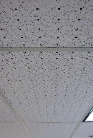
Laser-cut holes were thought to be simple and expedient, but left an undesirable charred odor. In the end, holes drilled on an automated 2-axis mill proved to be the best solution.
The next problem was to determine the number and size of the holes. Some of the longtime employees in the Facilities group thought the original tiles had 2% coverage of holes to the total area of the tiles, but no one was completely sure. Fortunately, a couple of tiles had not been thrown away and were found in a storeroom. Some tedious counting and measurement determined that the perforations did, indeed, cover 2% of the surface. An arbitrary hole size and resulting 10x30 grid pattern were selected and the ceiling tiles were drilled.
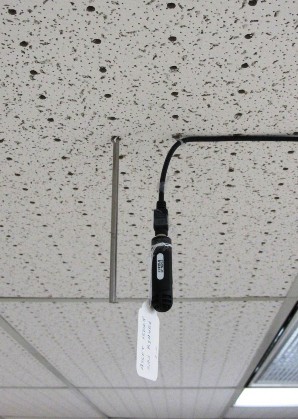
The newly-perforated ceiling tiles reduced the temperature pockets in the lab rooms. But this created a new problem. Since three of the four EPEL rooms had the Johnson Controls sensor positioned near the ceiling in the middle of the room, there was the concern that that “air wash” from the ceiling would provide temperature readings that were not representative of the entire room. This was easily solved by placing baffle plates above each sensor, thus eliminating the “air wash” condition near the sensors themselves. Another temperature gradient mapping of the lab rooms confirmed the adequacy of the air flow solution.
5 SUBSEQUENT ADJUSTMENTS
Once the lab staff was comfortable with the air supply arrangement and placement of the control sensors, it was decided to reduce the number of DewK sensors in each room to one, and to co-locate them with the control sensors. This served two purposes:
- Two recorded measurement points no longer provided extra advantage
- It was easier for Facilities to match the control sensors to the DewK sensors
A second change concerned the method by which the lab temperature and humidity data were recorded. At that point, LogWare was being used to record the EPEL temperature and humidity data, as well as that of the test labs in Temperature Calibration and Pressure Calibration within Fluke Park. Additionally, the Electrical Calibration areas were the last to still be monitored by the old NetDAQ system. Checking and managing it all was becoming an overhead burden, particularly with additional test benches being added in the Temperature Calibration group. A method to simplify this was sought.
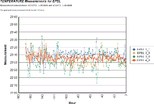
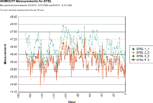
An agreement was made with administrators of FIS, a proprietary Fluke Factory Information System that records a large variety of inventory and production information. FIS was already being used to record temperature data from elsewhere within Fluke, and was expanded to include the EPEL DewKs, as well as most of the other DewKs within Fluke Park. Daily summaries of the lab’s temperature and humidity histories are available from FIS via email; see Figure 8.
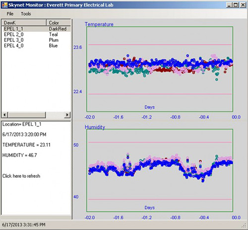
Additionally, an application was written that monitors the FIS data on a real-time basis, and allows downloading of select histories to a spreadsheet; see Figure 9.
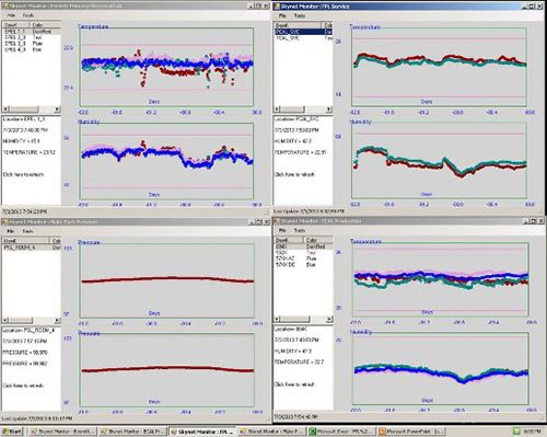
Finally, a large monitor was set up outside the lab. Several temperature-humidity plots of EPEL and the other labs are displayed there for all to see. This provides the state of environmental controls at a glance in Fluke Park Labs (Figure 10).
6 CONCLUSION
The air-conditioning system upgrade in EPEL was done out of necessity. A process was followed in which system requirements were first determined, and then translated into a design solution, and then into buy/refurbish decisions.
The lab downtime during the system upgrade was planned and coordinated with customers.
Equipment before- and after-checks were performed.
The lab was carefully brought back on-line, and a temperature gradient map was determined to evaluate the effectiveness of the new system.
An adjustment was made to the air delivery method in each room, which greatly reduced hot and cold pockets in the lab rooms.
Temperature and humidity recording was transferred to an enterprise database system which provides automated daily plots, but also allows real-time temperature/humidity monitoring and data downloading.
REFERENCES and ACKNOWLEDGEMENTS
ISO 17025, Section 5.3: Accommodation and environmental conditions
RP 14: Selecting Standards Lab Environments
Holaday-Parks, Inc. mechanical layout drawings 3315-1 and 3315-2, 8/1984
The Bowlin Company control system drawing CD-1, 6/1984
PSF Mechanical, Inc. mechanical layout & system drawings M-001, M-101, M-201, 9/2011
Private communication with Grace Giorgio and Tanky Shiu, Fluke Facilities Engineering Group
Private communication with Charlie Johns, Fluke Facilities Maintenance Group
Private communication with Jeff Gust, Neil Faulkner, Nicholas Mason & Dennis Destefan, Fluke Park Metrology
Related products
- Home
- Products
- New Products
- Electrical Calibration
- RF Calibration
- Data Acquisition and Test Equipment
- Temperature Calibration
- Humidity Calibration
- Pressure Calibration
- Flow Calibration
- Process Calibration Tools
- Calibration Software
- Service and Support
- All Calibration Instruments
- Handheld Test Tools
- Purchase Info
- News
- Training and Events
- Literature and Education
- Service and Support
- Service Request (RMA)
- Service Plans
- Technical Support
- Knowledge Base
- Accreditations
- Authorized Service Centers
- Calibration Certificates
- Community Forum
- My MET/SUPPORT
- Product Manuals (User Guides)
- Safety Data Sheets (SDS)
- Recycle Program
- Safety, Service, and Product Notices
- Software Downloads
- Warranties
- Tools
- About Us

